Appearance
Power Budget
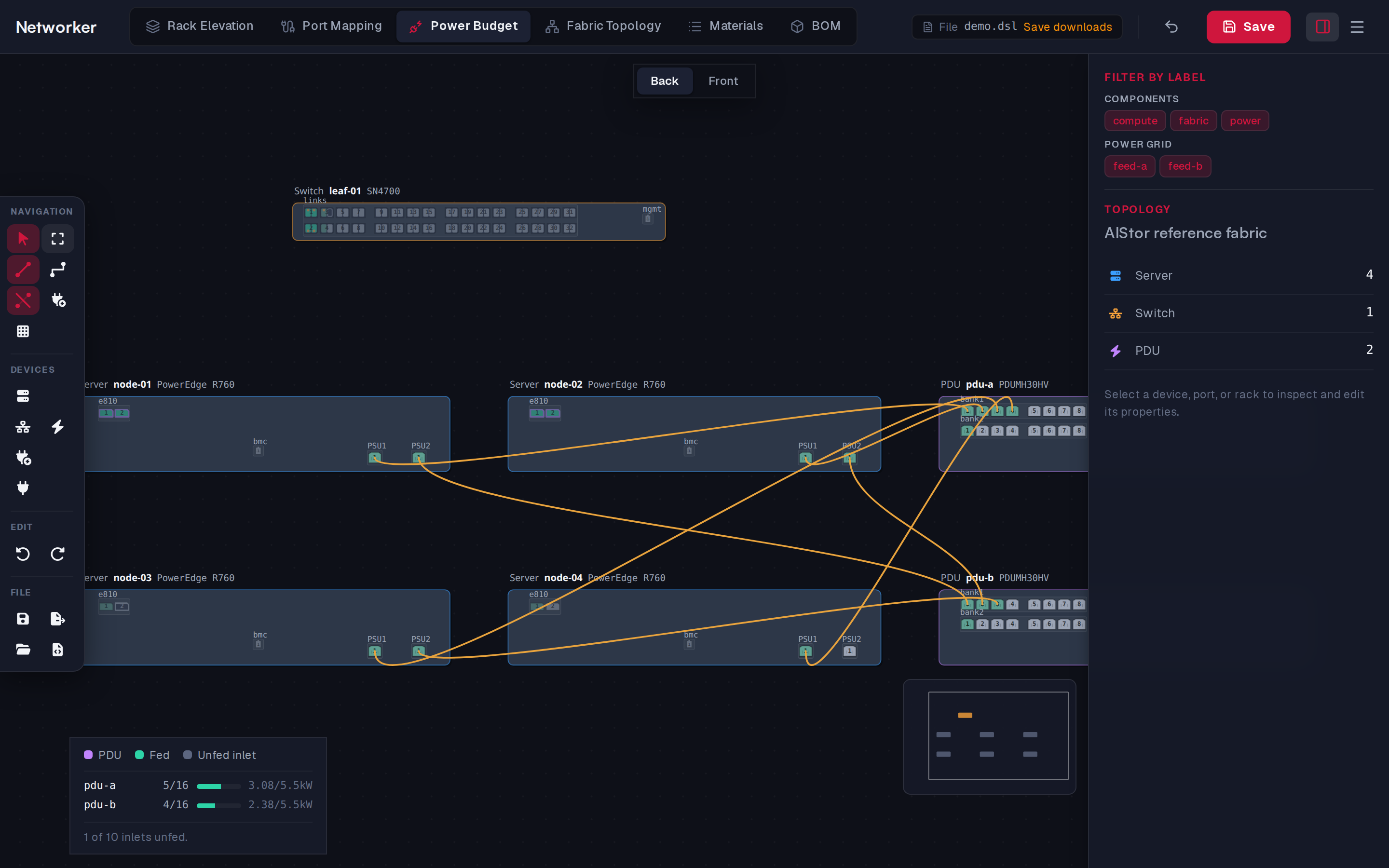
The same faceplate canvas as Port Mapping, but for power: here you add power inlets, draw power cords from PDU outlets to device inlets, and see how loaded each PDU is. Network ports and cables are shown read-only (and network cables start hidden).
What you can do here
| Task | How |
|---|---|
| Give a device a power inlet | 5 (Power inlet), click the device |
| Draw a power cord | C (Power cord), click a PDU outlet, then a device inlet |
| Set how much a device draws | Select the inlet port, set Draw (W) |
| Record a PSU serial number | Select the inlet, set PSU serial number |
| Label a cord (e.g. feed A / B) | Select the cord, add Labels; filter by them under Power grid |
| Show network or power cables | Show/Hide network cables, Show/Hide power cables |
A power cord always runs from exactly one PDU outlet to a power inlet. Selecting a network item here shows Read-only here. Network links and NICs are wired in the Port Mapping view.
The legend
The legend in the bottom-left corner reads:
- one row per PDU: its label, outlets in use / total (amber when all are used), a load meter, and the load against the capacity in kW. The meter turns amber above 80 % and red above 100 % of capacity;
- a footer: All N inlets fed, X of N inlets unfed, or a hint to add inlets when there are none.
How the load is calculated
Each inlet group's watts (its nameplate draw) is split evenly over its plugged-in cords and added to the PDU at the other end of each cord. A PDU's utilisation is that load divided by its Capacity (kW), set in the PDU template. A PDU without a capacity shows no meter.
In the DSL
Inlets are <Inlet> elements, outlets are <Phase> banks of a PDU, and cords are <PowerCable>:
xml
<PowerCable from="pdu-a/bank1/p0" to="node-001/PSU1/p0" length="1.8 m" labels="feed-a" />