Appearance
Port Mapping
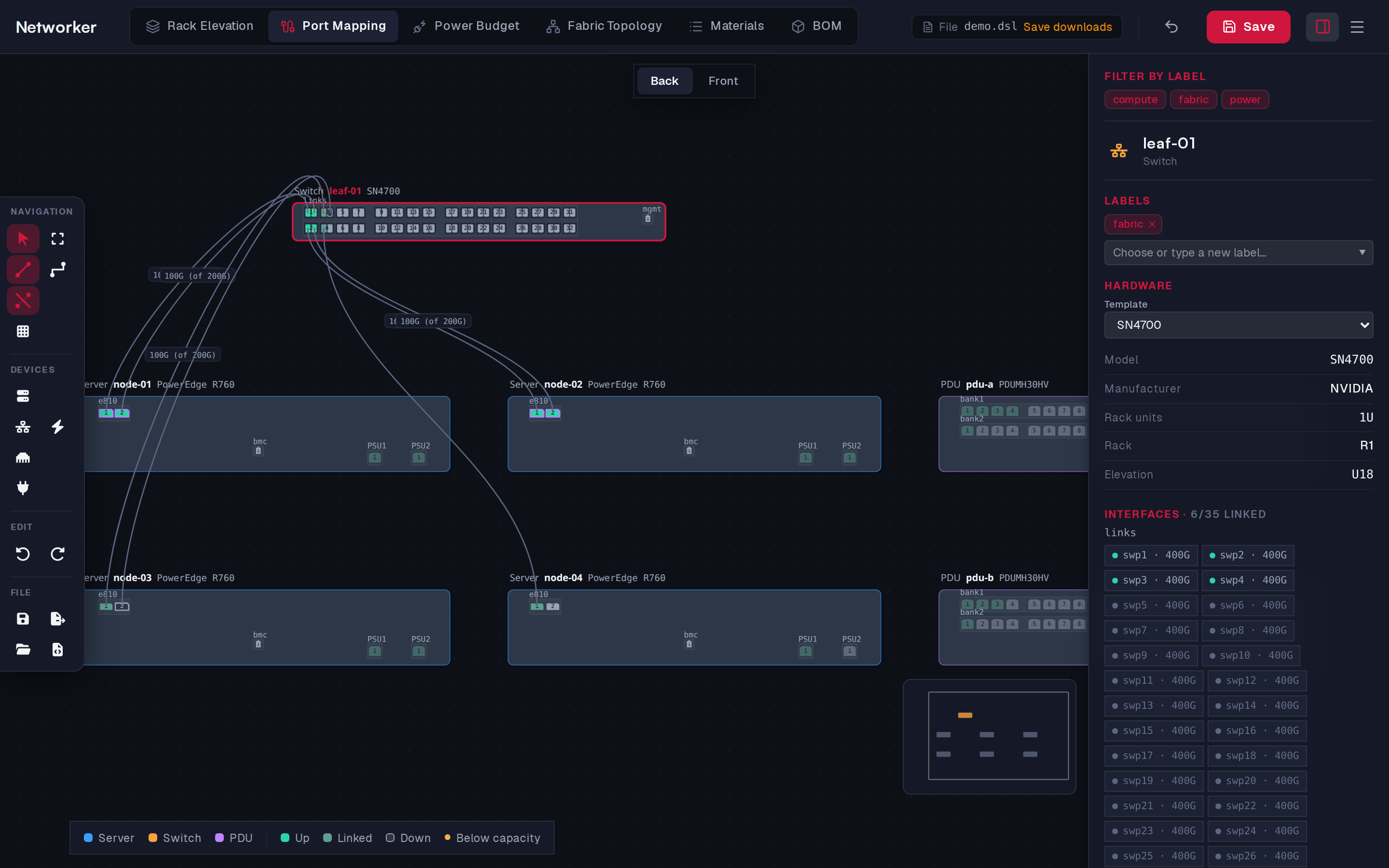
Every device drawn as its faceplate, to scale, with each NIC and port where it sits on the chassis. This is where the network is cabled. Power items are shown here read-only; they are wired in Power Budget.
What you can do here
| Task | How |
|---|---|
| Place a device | 1 / 3 / 4, then click the canvas |
| Add a NIC to a server | 5, then click the server |
| Draw a cable | C, click a port, click the other port |
| Draw N cables at once | C, + to set N, click the first port of each side |
| Split a switch port | Select the port, set Breakout to 2× or 4× |
| Bond ports | Select a port, Bond → + New bond, then add the other members |
| Record link state | Select the cable, set Link and Negotiated speed |
| Move a device | Drag its card |
| Arrange everything | Auto Layout (Ctrl+L) |
| Show the other face | Back | Front at the top |
See Adding items for the full cable workflow.
Showing cables
Network cables are hidden by default, because a full fabric hides the ports. Selecting a device, port or cable shows the cables that touch it. The Hide/Show Cables toolbar button shows them all. Straight / Orthogonal Cables switches how they are drawn.
Back and front
Only one face of the chassis is drawn at a time. Back | Front at the top switches it; NICs installed on the other face are hidden, and so are cables that don't have both ends on the face shown.
Port colours
The legend in the bottom-left corner explains them:
| Port | Meaning |
|---|---|
| Bright green | Cabled, link up |
| Muted green | Cabled, link state unknown |
| Hollow | Cabled, link down |
| Grey | Free |
| Small amber dot | Running below what it could (negotiated below the cable's capacity) |
| Purple outline | Member of a bond |
A breakout port is drawn as its lanes, each with its own colour. A cable with a negotiated speed is labelled with it, for example 100G (of 200G).
In the DSL
Cables are <Cable> elements; their ends are port paths such as leaf-01/links/swp1:0. A device's position on this canvas is its position.