Appearance
Materials (component) editor
The Materials tab is where hardware models are defined once — switches, servers, PDUs, NIC cards and cables — so that every device or cable placed from them is identical. In the DSL these are the entries of the <Catalog>.
The template lists
Materials has a tab per kind, each with how many templates it holds:
| Tab | Columns |
|---|---|
| Switches | Model, Manufacturer, Rack U, Power |
| Servers | Model, Manufacturer, Rack U, Ports, Uplink (fastest NIC), Connector, Power |
| PDUs | Model, Manufacturer, Rack U, Outlets, Capacity, Feed, Input |
| NICs | Model, Manufacturer, Ports, Speed, Connector |
| Cables | Model, Manufacturer, Speed, Connector, Material, Assembly |
- + New Switch (or Server, PDU…) creates a template of the selected kind.
- Click a model name, or the pencil, to edit it.
- The trash icon deletes it, after asking. Devices already placed from it are kept: they are written out in full in the file, and their panel shows the template as (missing).
Editing a template
The editor has the form on the left and a preview on the right. The header shows New / Edit <kind> and a back arrow.
Every kind has Model (required) and Manufacturer.
Switches, servers and PDUs
Rack Units — a slider (1–20) and a number box.
NIC Templates (Load Banks on a PDU) — one row per port group. + Add NIC (+ Add Bank) adds one: by default nicN with 2 × 10G RJ45 ports, or bankN with 8 C13 outlets behind a 20 A breaker. Each row has:
| Field | Values |
|---|---|
| Label | Unique within the device |
| Count | Ports (or outlets), at least 1 |
| Speed | Speeds, for data connectors |
| Branch breaker (A) | For power connectors (PDU banks) |
| Connector | Connectors. Choosing a power connector swaps Speed for Branch breaker |
| Port naming | A prefix and the first number. The default is p from 0 (p0, p1…); a preview shows the result, e.g. swp1…swp32. Spaces and : are not allowed |
| Back / Front | Which face of the chassis the group is on |
| Size (servers) | Custom size, OCP 3.0 SFF · 76 mm or OCP 3.0 LFF · 139 mm |
| × | Removes the group |
On servers, + From template… inserts a NIC from the NICs tab. Its row is locked to the NIC template (shown as model · N× speed connector); only its label, port naming and side can change.
Power (switches and servers) — + Inlet adds a power supply inlet, + Power cable a cord wired into the chassis. New ones are PSUn, one C14 inlet (and a 1.8 m cord when wired in). Each row: label, PSU model, inlet count, kind (Inlet / Power cable), connector (power connectors only), nameplate W, cord length (cables only), side, ×. A device needs an inlet to be fed from a PDU in Power Budget.
PDU electrical spec (PDUs):
| Field | Values |
|---|---|
| Phase | —, Single-phase, Three-phase |
| Voltage | Free text, e.g. 208/230V |
| Input (A) | Input current rating |
| Continuous (A) | Derated continuous rating; not above Input |
| Capacity (kW) | Used for the load meter in Power Budget |
| Input plug | A power connector, e.g. L6-30P |
| Cord length | Free text |
| Metering | —, Unmetered, Local meter, Network monitored |
| Outlets can be switched remotely | Checkbox |
The faceplate editor
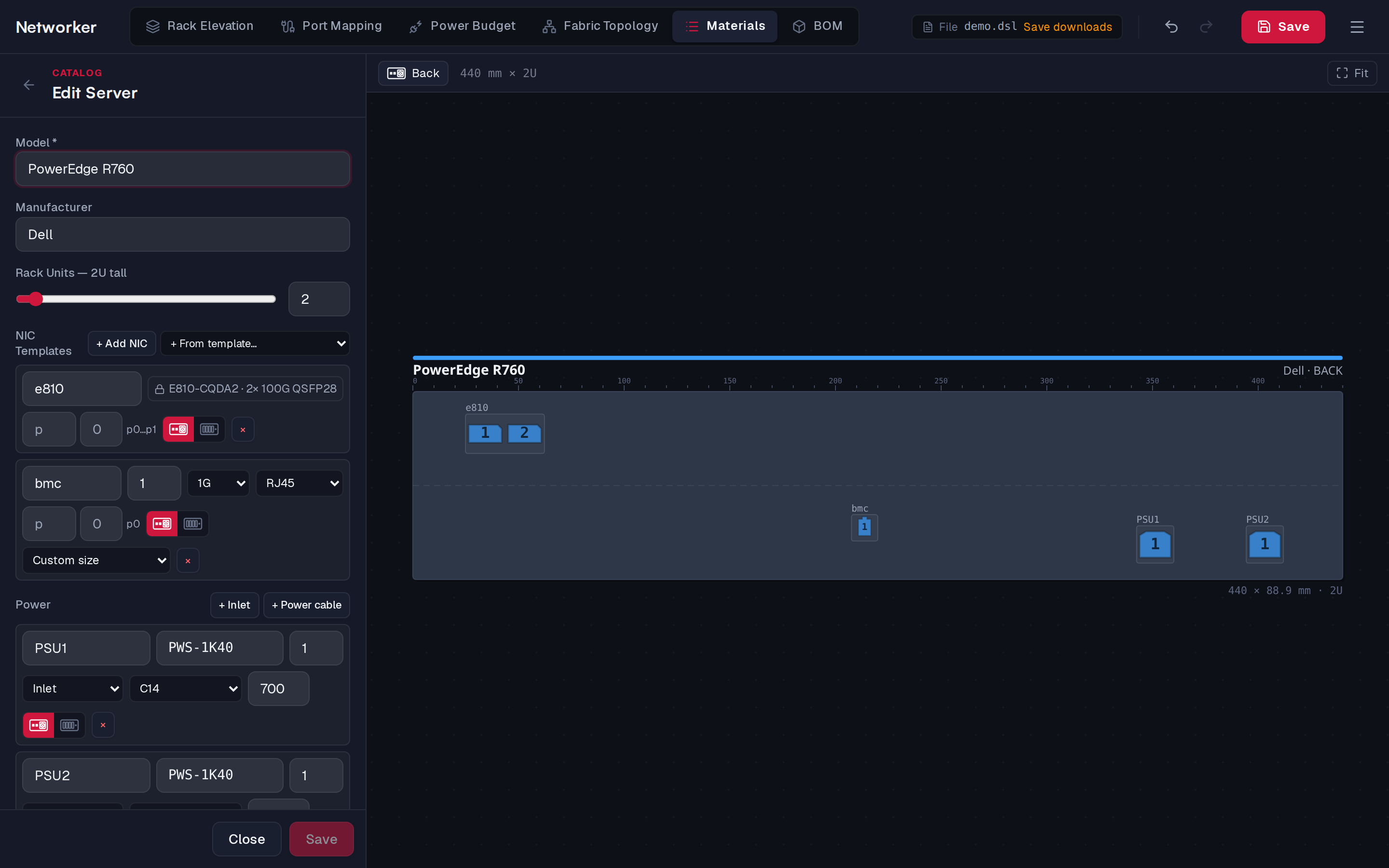
For switches, servers and PDUs, the right side draws the chassis to scale — always 440 mm wide, 44.45 mm per rack unit — with every port group where it sits. Sizes are shown in millimetres.
| Action | How |
|---|---|
| Zoom / pan | Scroll or pinch / drag the background. Fit re-fits |
| Show the other face | Flip device |
| Select a group | Click it. Shift+click adds to the selection |
| Move | Drag the selection; it moves in whole millimetres and stays on the faceplate |
| Resize | Drag the handles on the right edge, bottom edge or corner (one group selected) |
| Remove | Delete or Backspace |
Until you drag or stretch something, groups are laid out automatically (the faceplate says Drag or stretch a NIC to customize the layout).
On the back face, a toolbar edits the selected groups exactly:
| Field | Meaning |
|---|---|
| X, Y | Position, in mm |
| W, H | Box size in mm; leave empty to fit the ports |
| Rows, Cols | The port grid. They are linked so the grid always holds every port |
| Group | Put a gap after every N columns |
| Align | Left, Center or Right within a box wider than its ports |
| Facing | Alternate, All up, All down — which way each row of ports faces (more than one row) |
| Adjacent | With Alternate: how many rows in a block face the same way |
| Fit to ports | Shrink the box to its ports |
A field showing — means the selected groups differ. A group inserted from a NIC template can only be moved. These map to the layout object in the DSL.
NIC cards
The NICs tab defines cards that server templates insert with + From template….
| Field | Values |
|---|---|
| Port Count | At least 1 |
| Cols, Rows | The port grid (default: up to 8 columns, rows as needed) |
| Faceplate size | Fits its ports, OCP 3.0 SFF (76 × 11.5 mm), OCP 3.0 LFF (139 × 11.5 mm) |
| Speed | Speeds |
| Connector | Data connectors |
The preview draws the card to scale. Editing a NIC template updates every server template that inserted it.
Cables
| Field | Values |
|---|---|
| Speed, Connector | The cable's rated speed and connector |
| Material | —, Copper (DAC/ACC), Fiber (AOC). Changing it clears the assembly |
| Mode | —, Active, Passive |
| Assembly | Shown once a material is set |
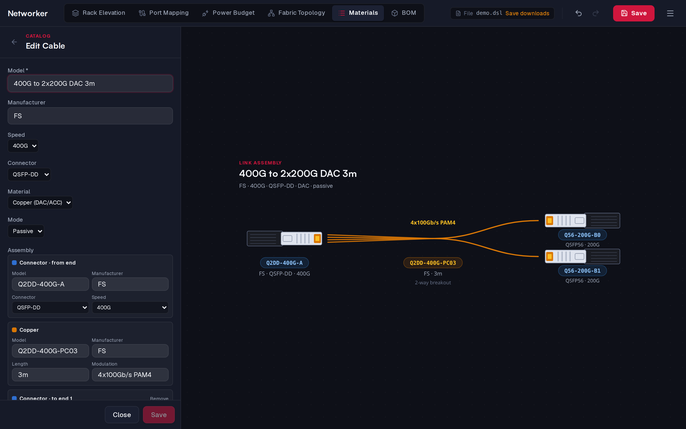
The assembly lists the parts, drawn as a diagram on the right:
- from end — Transceiver (fiber) or Connector (copper): Model, Manufacturer, Connector, Speed, and Modulation for fiber;
- the Fiber (Model, Manufacturer, Length, Connector — free text) or Copper (Model, Manufacturer, Length, Modulation) between them;
- one or more to end parts. + Add breakout transceiver / connector adds far ends for a 1→N breakout cable.
Serial numbers are not part of a template: they are recorded on each installed cable, in its properties panel.
Saving
- Save (or Ctrl+Enter, or Ctrl+S) saves the template and keeps the editor open. Pressing Ctrl+S again, with the template saved, saves the document.
- Cancel / Close leaves the editor. The back arrow asks what to do with unsaved changes (Save, Discard, Cancel).
WARNING
Esc and Cancel close the editor without asking, dropping unsaved changes to the template.
How templates affect placed devices
- Saving a device template rebuilds every device placed from it, straight away. Cables, bonds and per-port breakout changes are kept. One save is one undo step.
- Saving a NIC template updates the server templates that use it, and their devices.
- Saving a cable template updates every cable that uses it.
- Template changes are part of the document: save the document to keep them.
The quick template dialog
While placing devices, the catalog bar's + (and ✎ on a chip) opens a smaller dialog with the essentials: Model, Manufacturer, Rack Units, the NIC (or bank) rows, Speed and Connector, and Delete. Use the Materials tab for everything else, including the faceplate layout and power inlets.